Step 3: Design Iteration
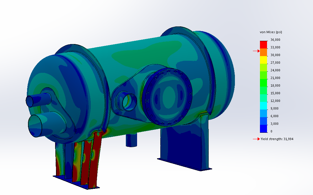
Observing the first pass stress results, we can immediately identify several areas of concern:
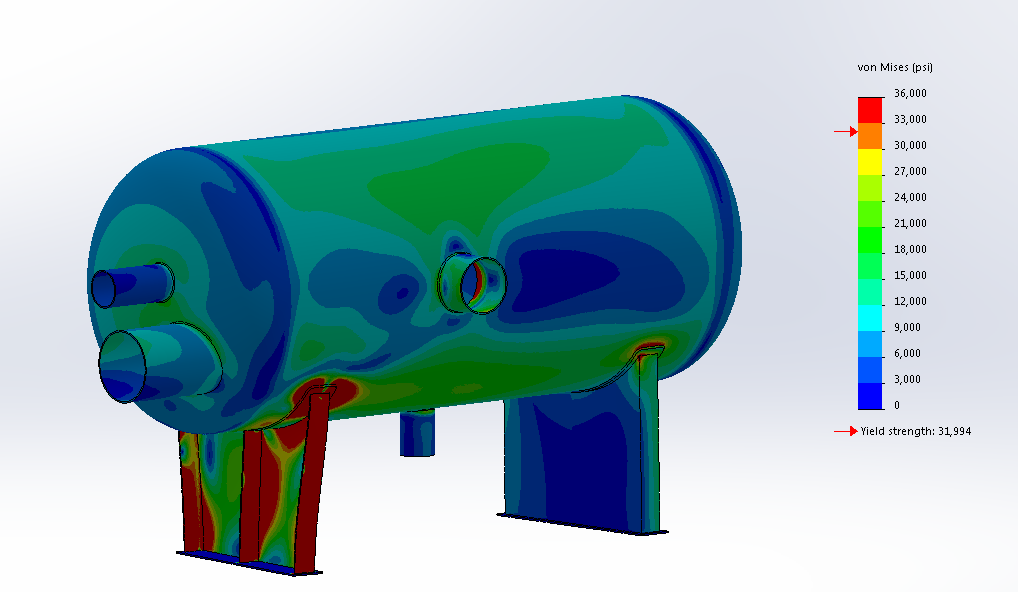
- The cylindrical body is moderately over our maximum allowable stress of 15.7ksi.
- Both nozzles located on the eliptical endcap have stresss concentrations at the weld connection.
- The saddle support, which is not free to slide, has insufficient lateral stiffnes and is showing unacceptable deformation.
- There are substantial stress concentrations located in the shell around the saddle repads.
- The nozzle located in the cylindrical shell has insufficient thickness in the nozzle itself and at the connection area.
- Additionally, ASME VIII Div 1, section UG-46 f(3) states that all pressure vessels over 36” diameter require a manway for inspection. This will have to be added.
We notify our client of these concerns, propose a series of possible solutions and make modifications to the simulation model. After conferring with our client and design engineers, we make a series of changes:
- A pair of stiffening rings were added in-plane with the support saddles.
- Two additional stiffeners in each support saddle and a wider repad were added to more evenly distribute the load.
- The side nozzle was moved over to make space for a 24” manway.
- A repad was added to both the front nozzle and the inspection manway. These repads overlap and were appropriately combined together.
- Similar to the front nozzle and manway, the two nozzles in the head received a merged repad.
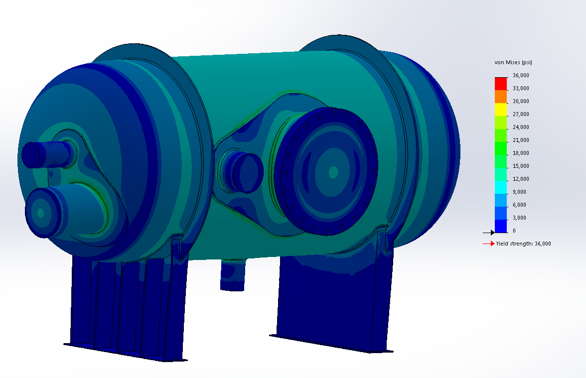
The FEA analysis was then repeated on the updated model and produced the following stress results:
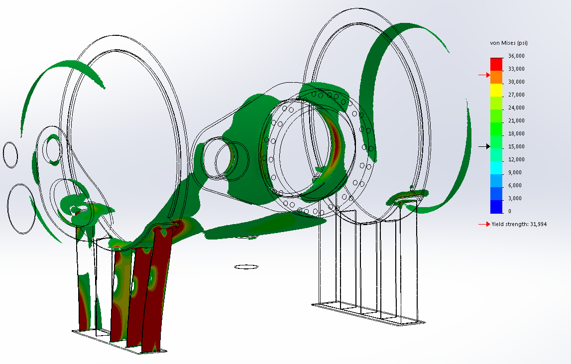
Our simulation tools have a variety of features to help make design decisions. The previous figure is called an iso-plot and shows only the portions of the model exhibiting material stresses higher than a specified value. In this case, areas above 15.7ksi. Comparing these stress levels with our previous design iteration we can evaluate the effectiveness of our changes and propose further actions:
- The stiffening rings drastically reduced the average stress level in the vessel shell. There is still a small area of concern around the drain nozzle.
- The additional saddle stiffeners and wider saddle succeeded in strengthening the sliding saddle support.
- The saddle has lower stress levels, but remains undersized. Here we realize that having two symmetric saddles is no longer feasible. The fixed saddle requires more reinforcement compared to the sliding saddle as the fixed saddle alone must resist the axial loads imposed on the vessel.
- No fixtures were applied to sliding saddle to constrain it from twisting relative to the fixed saddle. This is further increasing the stress levels within the fixed saddle by unreasonably subjecting it to excess torsion.
- The area around the manway and side nozzle remains over the acceptable stress level with a notable concentration along the horizontal midline.
- There are small rings of medium stress on the inside surface at the “knuckle” of each shell head.
- Minor stress concentrations exist at the repad-to-nozzle connection in the head nozzles.
Using this information, our designers are equipped to propose a number of changes:
- Through intuition and experience, we recognize that the stress pattern around the drain nozzle is a result of the roller/slider fixture applied to the nozzle face. The nozzle is free to move along the length of the vessel but is entirely restrained in the vertical direction. When the shell sags, under the combined weight of the shell itself and the contained fluid, the drain nozzle is trying to support the entire center span of the vessel. For the next iteration we will remove this restriction and allow the nozzle to move. We will also advise our client to connect the drain with flexible piping, such as an expansion joint or a couple of elbows, to relieve the nozzle load. As a side effect, the pressure vessel goes from being essentially a beam supported at three points to a beam supported at two points. The saddles need to be moved closer together to reduce the effective span and strengthened to handle the increased load.
- The fixed saddle has received thicker and deeper reinforcement gussets.
- The sliding saddle has been constrained to only allow translation along the length of the vessel which is representative of slotted connections.
- With the new manway as a means of accessing the inside of the vessel, we are free to weld the internal nozzle projection to the shell instead of just the outside. This provides additional reinforcement to the manway and side nozzle.
- We will apply a smaller mesh element size to all nozzle connections. These abrupt changes in geometry produce stress concentrations that are not accurately captured with a coarse mesh size.
- The nozzles will be artificially capped to allow the internal pressure to balance in all directions. This will artificially increase the axial stress along each nozzle but we can be confident making this simplification because we have already verified each nozzle to be of sufficient strength.
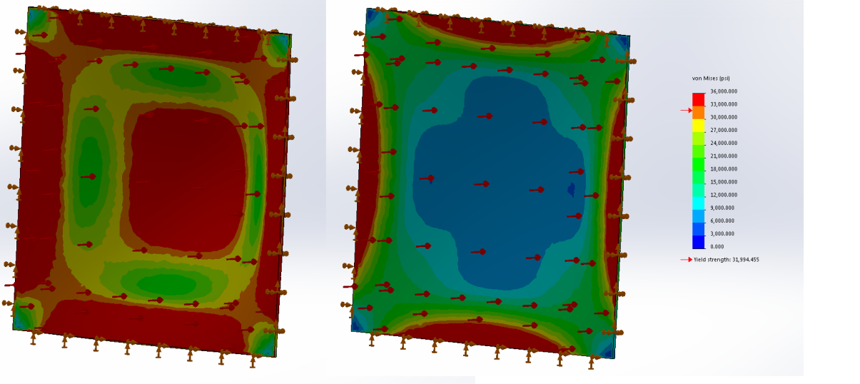
- To properly evaluate the stress levels in the vessel heads, we need to change the simulation’s solver algorithm to Large Displacement mode. The current solver takes 100% of the loads and applies them to the model all at once, then evaluates the deformation and stress relative to the initial model. This method loses accuracy when large deformations exist, and especially when the deformed shape is stiffer than the un-deformed shape. A textbook example of this situation is a flat plate, secured around the perimeter, with a pressure applied to the face. The un-deformed plate has almost no ability to resist the pressure imposed onto it. However, once it deforms slightly into a domed shape, it becomes much stiffer due to its ability to resist the load through membrane stresses. The new algorithm evaluates this phenomenon by applying a portion of the load, evaluating the stress levels and updating the analysis with the new stiffness of the deformed shape. Then another portion of the load is added, the simulation repeats, the stiffness is updated and so on. This effectively runs a number of simulations in series and can be much more time-consuming; therefore, we only run this method when necessary. To illustrate, refer to the following figures. This shows a 2’ x 2’ x ¼”thk square plate under a pressure of 40psi. Note the lower stress values reported in the simulation depicted on the right which uses the Large Displacement mode method and produces much more accurate results
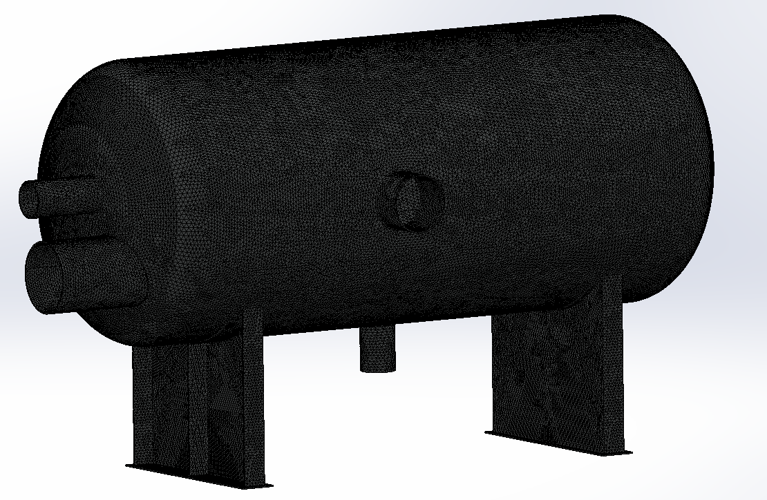
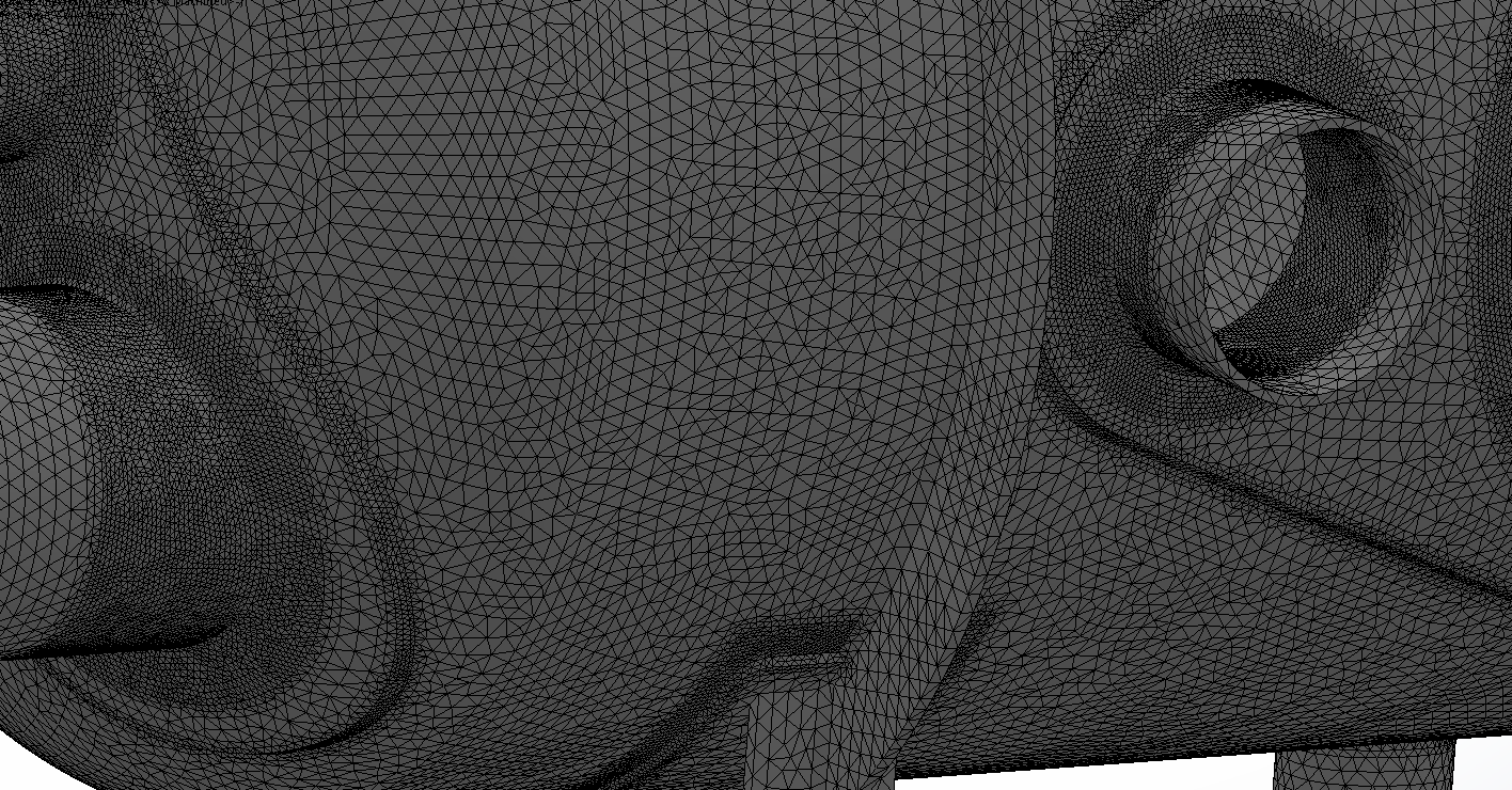
The following figure shows the new mesh. Mesh density was increased locally around the nozzle and re-pad connections, and coarsened elsewhere to help keep computation time down. For reference, this simulation is solving a large, complex problem by breaking it up into approximately 1 million small tetrahedron elements.
The third-pass simulation results showed the following:
- First and foremost, we can clearly see reduced stress levels in the fixed saddle from properly balancing the internal pressure and constraining the sliding saddle down to one degree of freedom.
- Without the drain nozzle supporting the center of the vessel, the average stress in the cylindrical shell has increased but remains within acceptable levels.
- The new simulation algorithm was able to more accurately evaluate the stress levels in the elliptical heads. This did not come without a cost. For reference, the simulation used to run in 5 minutes but now takes around 75 minutes