Business Problem
Our client had developed a proprietary biomass thermal reactor designed for large scale production of renewable pipeline grade natural gas. Forestry waste product is used as the primary fuel and converted to natural gas through a thermochemical process. In order to be deemed fit for service, the design was required to be analysed per Section XIII Div 2 of the ASME Boiler Pressure Vessel Code (BPVC). The analysis is used in order to determine the maximum number of thermal cycles that the reactor vessel could safely withstand and was an important project for our client as the results supported the registration of the vessel within the jurisdiction of its intended location.
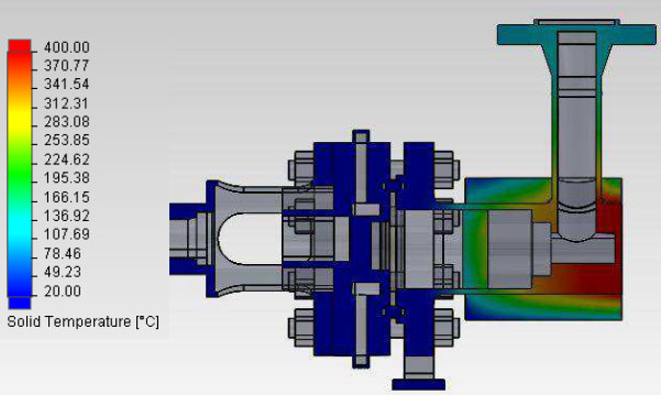
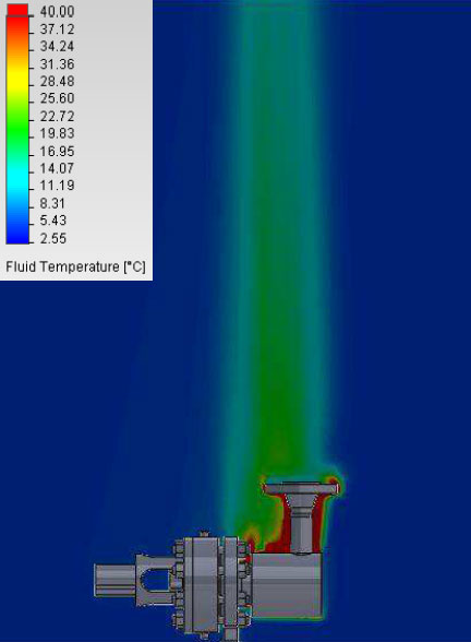
Cut section showing thermal distribution in steel body components during normal operation